Tool Change and Setup Procedure
Details Tools Required Torque Chart Points of Attention| Activity Number: | 0929202201-01 |
|---|---|
| Frequency: | As Needed |
| Execution Time: | 60 Minutes |
| Machine Status: | Dynamic |
| Activity Type: | Machine Setup Procedure |
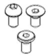
| Nominal Diameter |
Hexagon socket head bolt (steel) |
Hexagon socket head bolt (stainless) |
Hexagon socket head button bolt Hexagon socket head flush bolt Low-head bolt (steel) |
Hexagon bolt (steel) | ||||
|---|---|---|---|---|---|---|---|---|
| Tightening torque | Tightening torque | Tightening torque | Tightening torque | |||||
| Upper Limit | Lower Limit | Upper Limit | Lower Limit | Upper Limit | Lower Limit | Upper Limit | Lower Limit | |
| M3 | 1.8 | 1.3 | 0.76 | 0.53 | -- | -- | -- | -- |
| M4 | 4.0 | 2.8 | 1.8 | 1.3 | 1.8 | 1.3 | 1.7 | 1.2 |
| M5 | 7.9 | 5.6 | 3.4 | 2.5 | 4.0 | 2.8 | 3.2 | 2.3 |
| M6 | 14 | 9.6 | 5.8 | 4.1 | 7.9 | 5.6 | 5.5 | 3.8 |
| M8 | 32 | 23 | 14 | 9.8 | 14 | 9.6 | 13 | 9.3 |
| M10 | 66 | 46 | 27 | 19 | 32 | 23 | 26 | 19 |
| M12 | 110 | 78 | 48 | 33 | -- | -- | 45 | 31 |
| (M14) | 180 | 130 | 76 | 53 | -- | -- | 73 | 51 |
| M16 | 270 | 190 | 120 | 82 | -- | -- | 98 | 69 |
| (M18) | 380 | 260 | 160 | 110 | -- | -- | 140 | 96 |
| M20 | 530 | 370 | 230 | 160 | -- | -- | 190 | 130 |
| (M22) | 730 | 510 | -- | -- | -- | -- | -- | -- |
| M24 | 930 | 650 | -- | -- | -- | -- | -- | -- |
| (M27) | 1400 | 960 | -- | -- | -- | -- | -- | -- |
| M30 | 1800 | 1300 | -- | -- | -- | -- | -- | -- |
| M36 | 3200 | 2300 | -- | -- | -- | -- | -- | -- |
 |
 |
 |
||||||
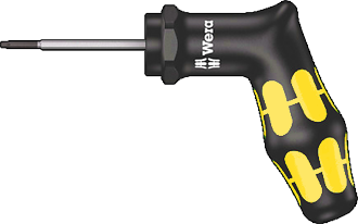
- Torx Torque Screwdrivers (T9, T10, T25)
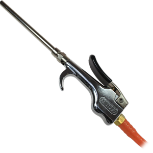
- Air Hose with Nozzle Attachment
- Permanent Marker
- Absorbent Towels
- Gaging Tools (various - not shown)
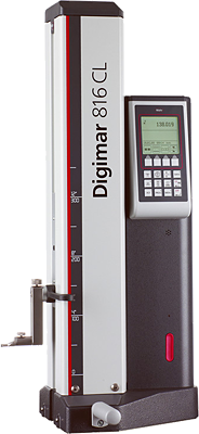
- Digimar Height Measuring Instrument with Base Ring


Make sure you are wearing proper PPE before beginning this maintenance activity. Refer to plant and department specific PPE requirements.
If you are unclear how to preform this task, ask your supervisor.
While performing this PM, if you discover any problems that are outside the scope of the work covered by this PM, generate a work ticket to initiate the necessary repairs AND report to your supervisor.
If this PM is not accurate please document any changes or additions that should be made and give them to your supervisor.