HPD Nozzle Cleaning Procedure

Details Tools Required Torque Chart Points of Attention
Expand All
Nominal
Diameter
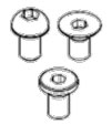
Hexagon socket head bolt
(steel)
Hexagon socket head bolt
(stainless)
Hexagon socket head button bolt
Hexagon socket head flush bolt
Low-head bolt
(steel)
Hexagon bolt (steel)
Tightening torque Tightening torque Tightening torque Tightening torque
Upper Limit Lower Limit Upper Limit Lower Limit Upper Limit Lower Limit Upper Limit Lower Limit
M3 1.8 1.3 0.76 0.53 -- -- -- --
M4 4.0 2.8 1.8 1.3 1.8 1.3 1.7 1.2
M5 7.9 5.6 3.4 2.5 4.0 2.8 3.2 2.3
M6 14 9.6 5.8 4.1 7.9 5.6 5.5 3.8
M8 32 23 14 9.8 14 9.6 13 9.3
M10 66 46 27 19 32 23 26 19
M12 110 78 48 33 -- -- 45 31
(M14) 180 130 76 53 -- -- 73 51
M16 270 190 120 82 -- -- 98 69
(M18) 380 260 160 110 -- -- 140 96
M20 530 370 230 160 -- -- 190 130
(M22) 730 510 -- -- -- -- -- --
M24 930 650 -- -- -- -- -- --
(M27) 1400 960 -- -- -- -- -- --
M30 1800 1300 -- -- -- -- -- --
M36 3200 2300 -- -- -- -- -- --
  • Combination Wrench Set
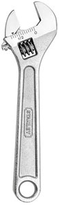
  • Adjustable Crescent Wrench
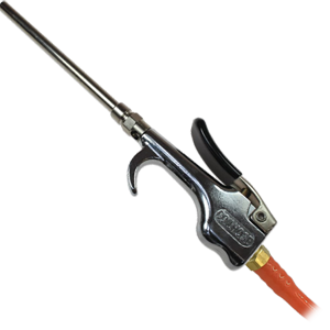
  • Air Hose with Nozzle Attachment
  • Cleaning Solution (lye based)
  • Container for Cleaning Solution
  • Absorbent Towels

Make sure you are wearing proper PPE before beginning this maintenance activity. Refer to plant and department specific PPE requirements.

Lockout all stored energy sources in the work area using proper procedure. Review lockout placard and follow plant lockout procedures.

If you are unclear how to preform this task, ask your supervisor.

While performing this PM, if you discover any problems that are outside the scope of the work covered by this PM, generate a work ticket to initiate the necessary repairs AND report to your supervisor.

If this PM is not accurate please document any changes or additions that should be made and give them to your supervisor.

1: Shut the machine down. Go to the HMI panel, at the Machine Start-Up Screen – Pg 2, shut off the Blowoff Fan #1, High Pressure (HP) Pump, Booster Pump, Deburr (DBR) Filter Pump, and Hydraulic Pump.

2: Once everything is shut down, push in the Emergency Stop (E-Stop) button on the HMI Control Panel. Place a hasp and personal lock on the E-Stop lockout point to lockout the system.

Note: Follow all ECPL procedures attached to the machinery.

3: Remove the nozzles. Using a 13/16 inch crescent (or open end/box end) wrench remove the nut and nozzle by turning counter-clockwise.

4: Remove the internal screen.

5: Repeat steps 3 and 4 to remove all nozzles and screens on the Hydro-Jet.

6: Place all removed nuts, nozzles, and screens in a properly labeled container of lye based cleaning solution to soak to remove corrosion buildup on the screens.

7: While screens and nozzles are soaking in cleaning solution, insert air hose into the nozzles and blow air (set to safe plant specified PSI) while at the same time, feeling the opposite nozzle to check that air is coming out. If you feel air, the Hydro-Jets are clear.

Note: Make sure to use appropriate PPE.

8: Repeat step 7 for each nozzle. Once completed making sure all nozzles are clear, the nozzles and screens are ready to be reinstalled.

9: Once the screens and nozzles have been cleaned, the nozzles are ready to be checked to verify the opening has been cleared by blowing a squirt of air through the back of it, using your finger to feel the air coming out of the nozzle.

Note: Make sure to use appropriate PPE.

10: Repeat step 9 for each nozzle. Once completed making sure all nozzles are clear, the nozzles and screens are ready to be reinstalled.

11: First install the screen.

12: Then install the nut with the nozzle.

13: Note: When installing and tightening the nozzle and nut onto the Hydro-Jet, make sure the rectangle shape of the nozzle opening is perpendicular to the outside edge of the Hydro-Jet.

Hand install the nozzle and nut onto the Hydro-Jet.

14: Using a 13/16 inch wrench, snug the nut.

15: If the nozzle is not perpendicular to the Hydro-Jet edge, use a smaller open end wrench or crescent wrench on the nozzle to turn until the rectangular shape is perpendicular to the outside edge of the Hydro-Jet.

16: Repeat steps 13~15 for each remaining nozzles making sure the rectangle shape of the nozzle opening is perpendicular to the outside edge of the Hydro-Jet.

Once all nozzle installation has been completed; the machine is ready to be started.

17: Proceed to the HMI Control Panel, remove your personal lock and hasp from the E-Stop pushbutton. Then pull the E-stop button out.

Note: Clear any faults by pressing the Fault Reset button on the HMI Control Panel.

18: Restart the machine by pressing the appropriate F-Key at the Machine Start-Up Screen – Pg 2 in the following order: Start HYD (Hydraulic) Pump F1, Start Filter Pump F2, Start Booster Pump F3, Start Blowoff F5, Start HP (High Pressure) Pump F4.

Note: Once pressed, the onscreen button indicators will flash during startup, make sure they turn solid green before proceeding.