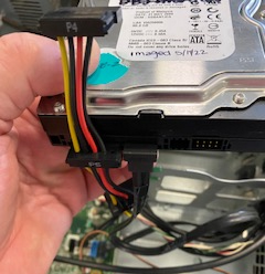
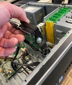
Hard Drive Replacement
Details Telesis Computer Setup Information Points of Attention| Frequency: | As Needed |
|---|---|
| Execution Time: | 20 Minutes |
| Machine Status: | Static |
| Activity Type: | Electrical |
| Dept | Description | Sta | Brass Tag | Pattern Loaded | Merlin Host IP | PC Nic | Subnet Mask |
|---|---|---|---|---|---|---|---|
| 5900 | Main Line | 65 | AAA373612 | PAT08.TTP | 10.177.222.225 | 10.177.22.232 | 255.255.248.0 |
| 5910 | RS3 Carrier | 20 | AA369833 | PAT07.TTP | 10.177.236.223 | 10.177.236.228 | 255.255.254.0 |
| 5910 | RS4 Carrier | 20 | AA369833 | PAT07.TTP | 10.177.236.223 | 10.177.236.229 | 255.255.254.0 |
| 5910 | RS1 / RS2 Carrier | 20 | AA369822 | PAT08.TTP | 10.177.234.233 | 10.177.234.228 | 255.255.254.0 |
| 5920 | Output Gear Assembly | 10 | AA372582 | PAT08.TTP | 10.177.231.229 | 10.177.231.236 | 255.255.254.0 |
| 5930 | Gear Train | 10 | AAA372582 | PAT08.TTP | 10.177.227.140 | 10.177.227.147 | 255.255.254.0 |
| 5940 | Valve Body Assembly | 30 | AA367947 | PAT07.TTP | 10.177.229.140 | 10.177.229.147 | 255.255.254.0 |
| 5950 | Bell Housing | 32 | AAA372692 | PAT08.TTP | 10.177.233.103 | 10.177.233.108 | 255.255.254 |
- Combination Wrench Set
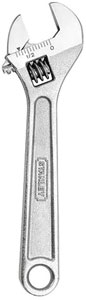
- Adjustable Crescent Wrench
- Air Hose with Nozzle Attachment
- Cleaning Solution (lye based)
- Container for Cleaning Solution
- Absorbent Towels


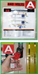
Make sure you are wearing proper PPE before beginning this maintenance activity. Refer to plant and department specific PPE requirements.
Lockout all stored energy sources in the work area using proper procedure. Review lockout placard and follow plant lockout procedures.
If you are unclear how to preform this task, ask your supervisor.
While performing this PM, if you discover any problems that are outside the scope of the work covered by this PM, generate a work ticket to initiate the necessary repairs AND report to your supervisor.
If this PM is not accurate please document any changes or additions that should be made and give them to your supervisor.